The Evolution of
802.11 Wireless Security
INF 795 - Kevin Benton
April 18th, 2010
This paper covers a brief history of the wireless protocols that led up to the creation of the 802.11 networks that drive the consumer and corporate wireless data networks today. It then briefly details how the different common types of 802.11 networks operate.
After the basic network functionality, it covers the details of each type of privacy algorithm and authentication procedure offered by the standard along with known associated vulnerabilities.
The following diagram is provided as a reference to illustrate the timeline of the protocols and vulnerabilities covered in this paper:
"802.11 Wireless Security Timeline" - Kevin Benton
This document is broken into major sections which are designated by roman numerals in the table of contents. All of the references are contained in the references section of the major section that they pertain to.
Up until 1985, wireless data networks didn't have widespread popularity due to licensing restrictions. The ISM bands that all of the unlicensed radios use today were not opened for use to the public until 1985. In order to run a wireless network before then, a license had to be obtained from the FCC and hardware had to be built to operate on the leased frequency.
Once the ISM band was opened for spread-spectrum technology, many companies began racing to create wireless hardware compatible with existing data networks. Each technology was vendor specific so all of the hardware had to be manufactured by the same vendor to function correctly. It quickly became clear that a standard would be needed if any of the products were going to operate between vendors.
Wireless stations operating on the same frequency have to overcome the challenge of sharing a medium. In 1970, the University of Hawaii developed the first random access method that allowed devices to share a communications medium.[II.1] There were two versions of the protocol: Pure ALOHA, and Slotted ALOHA. Slotted ALOHA was released to fix major inefficiencies in Pure ALOHA.
The ALOHA protocol eventually evolved into CSMA/CD(Carrier Sense Multiple Access with Collision Detection) and CSMA/CA(Carrier Sense Multiple Access with Collision Avoidance). Both of these protocols are currently used in both wired(CSMA/CD) and wireless(CSMA/CA) networks. [II.1]
Pure ALOHA was the first random access multiple-access protocol for data networks. In random access protocols, all of the stations have equal priority and there is no central method of control.
One of the important functions of a random access protocol is to determine how to handle collisions. Since there isn't a central point of control, multiple stations may transmit at the same time, resulting in an incomprehensible message for the receiver.
Pure ALOHA handles collisions by using acknowledgements from the receiving station. If a transmitting station doesn't receive an acknowledgement from the receiving station within a timeout window, the message is considered lost. The sender then waits a time-out period plus a small random amount of time before retrying the transmission. The random time is required to help avoid two stations from transmitting at the same time again.[II.1]
Finally, if the sender fails to receive an acknowledgement after several transmission attempts, the frame is considered lost. This prevents the channel from becoming overly congested by constant retransmissions to a station that may not even be online.
The ability for any station to transmit whenever it has data makes pure ALOHA very vulnerable to collisions. Accordingly, the maximum successful packet rate is 18% of the total transmissions. [II.2]
In order to improve the efficiency of pure ALOHA, slotted ALOHA implements transmission windows that the stations are restricted to. By setting windows when each station can transmit, it greatly reduces the vulnerability a frame has to a collision. The only time a collision can occur is when multiple stations choose the same time slot. The following diagrams illustrate the difference between the two protocols.
"Pure ALOHA and Slotted ALOHA" - Kevin Benton
With the new timing restrictions on transmissions, slotted ALOHA has a successful transmission rate of about 38%. [II.1] While this success rate is relatively low, ALOHA pioneered the field of research in sharing a physical medium between multiple nodes. The CSMA/CD(used in ethernet) and CSMA/CA(used in 802.11) access protocols were derived from ALOHA.[II.1]
Fritzt Gfeller and Urs Bapst published a paper in 1979 outlining a protocol for wireless communication between devices in the same room using infrared diffusion.[II.3]
The primary purpose of the protocol was to allow several terminals in a room to communicate with a single host computer. The host/mainframe could be located in a different location; however, it would be need to be wired to a transmitter in the same room as the terminals that it needed to communicate with.
The limitations of the protocol are primarily do to its use of infrared radiation for communication. Infrared is very near visible light and carries many of the same properties. The two limiting factors are its emission by heat sources such as the sun and its inability to pass through solid objects.
Direct line of sight wasn't required for the protocol to function correctly. It relied on the diffusion of the infrared sent out by the transmitter. The same effect can be observed with light from a light bulb. Even if a person can't see the light bulb itself, he/she can see the light from the bulb on most of the objects in a room.
The protocol had a theoretical maximum of 260 megabits per second; however, due to background infrared interference from daylight limited the rates to less than 1 megabit per second. The experimental links they tested their protocol with produced rates of 125 kilobits per second when using pulse code modulation and 64 kilobits per second using phase-shift keying.
This protocol was an important step towards wireless networks today because it did not require a license to operate. The ISM band used by 802.11 networks today had not yet been opened up by the FCC so there were no other options for unlicensed wireless data communications.
In 1980, Walter Scales published the paper "Potential Use of Spread Spectrum Techniques in Non-Government Applications". [II.4] As the name suggests, spread spectrum techniques were not being used for anything other than military and aerospace applications.
Spread spectrum works by taking a transmission and spreading it out over a wide range of frequencies. This technique has the following advantages over transmitting on one frequency:
The paper provided a compelling argument for the FCC to open up bands of the spectrum to the public to be used with spread spectrum technologies. While the security aspect was not a major push, the advantage of many users being able to share a single range of bandwidth interested the FCC.
On 1981, the FCC issued a Notice of Inquiry to conduct research in the general civil use of spread spectrum technologies. This temporarily granted the Amateur Radio Research and Development Corporation the ability to use spread spectrum technologies.[II.5]
In 1984, the FCC release a Notice of Proposed Rulemaking that proposed the authorization of the use of spread spectrum technologies under conditions that didn't interfere with other users of the same spectrum.[II.5]
Finally, in 1985 the FCC authorized the use of spread spectrum technologies in the "Industrial, Scientific, and Medical"(ISM) band. The ISM band includes the following frequencies: 902-928 MHz, 2400-2483.5 MHz, and 5725-5850 MHz. The FCC determined that these bands were currently not used for communications and they provided enough bandwidth to develop high data rate technologies. Users would be allowed to use this band with transmission powers up to 1 watt.[II.5]
One of the reasons the ISM band was chosen to test spread spectrum was because of the various sources of interference introduced into those frequency ranges. Microwave ovens, MRI equipment, and several other industrial devices use the wavelengths in the ISM band to accomplish a purpose other than communication. Without spread spectrum, the band would be unusable because of these sources.[II.6]
The ISM band allowed the creation of many devices consumers enjoy today. Cordless phones, Bluetooth, and 802.11 networks all use the ISM band.
In 1988, the IEEE established a committee to develop the 802.11 standard.[II.7] All of the 802 standards deal with the data link layer and physical layer of the OSI reference model. Part 11, or 802.11, defines all of the specifications for wireless local area networks.
The IEEE 802.11 committee held two wireless LAN workshops before actually releasing the first version of the standard in 1997. The purpose of these workshops was to facilitate communication and interaction between the researchers and developers working on wireless technology. It helped attendees understand where most of the technology was and where the future of wireless LANs was going.[II.8]
The amateur radio groups released modems after the FCC opened up the ISM band. These initial spread spectrum data modems provided rates up to a few hundred kilobits per second. By the time the first IEEE workshop came in 1991, several companies were working on radios compatible with existing LANs with rates in the low megabit per second range. [II.9]
By the time the second workshop was hosted in 1996, the development of the 802.11 standard was under way and the competing European standard Hiperlan 1 was just published. Some of the topics discussed at the the workshop included security and networks in the 5 GHz ISM band.[II.10]
The HiperLAN standard was released in Europe by the European Telecommunications Standards Insitute (ETSI) in 1996 and then revised in 2000. It is no longer advancing today due to the spread of the 802.11 standard across the world.[II.11] At the time of its release, it offered a higher data rate than the proposed 802.11 standard at 23 Mbps when the initial 802.11 standard
maxed out at 2 Mbps.
The initial 802.11 standard was finally released in 1997 and it offered 3 methods of access that all operated at 1 to 2 megabits per second.[II.12]
This initial standard was quickly outdated by the 802.11a and 802.11b standards; however, it was the start of the most widely used wireless LAN protocol today.
All of the security protocols covered in this document pertain to the devices operating based on the 802.11 wireless standard. To provide a background of the protocol and its general operation, this section will cover the specifications of the different speed revisions of 802.11 networks.
The security protocols associated with the standard can be found in the next two major sections. This section is provided to give a basic overview of how the wireless networks function without regard to the security.
There are two units that the wireless protocols perform functions on: the MAC Service Data Unit (MSDU) and the MAC Protocol Data Unit (MPDU). The MSDU is the payload received from the upper layer of the OSI. An example of an MSDU would be an IP datagram or an ARP datagram. If an MSDU is larger than the maximum payload size of the 802.11 MPDU (18,432 bytes), it will be fragmented and carried by multiple MPDUs.
The MPDU, often referred to as a frame, contains the MSDU, the MAC addressing information, the frame length, and the frame correction sequence in the form of a CRC-32 hash.[III.1] The following diagram illustrates the MPDU format:
"MPDUs and MSDUs" - Kevin Benton
Although the frame format is very similar to Ethernet frames, there are a few extra fields. 802.11 was designed to be compatible with Ethernet networks. By maintaining very similar frame structures, converting 802.11 frames to Ethernet frames is a relatively simple task.[III.2]
The four address fields are used differently depending on the the frames source and destination. There are four different situations that dictate different uses of the address fields. The following table shows the values for each situation.
Frame Path | Address 1 | Address 2 | Address 3 | Address 4 |
Frame between two wireless clients | Destination MAC | Source MAC | BSSID | N/A |
Frame from network through AP to Client | Destination MAC | AP's MAC | Source MAC | N/A |
Frame from client to network through AP | BSSID | Source MAC | Destination MAC | N/A |
Frame traveling between two APs in a WDS | Receiving AP's MAC | Transmitting AP's MAC | Destination MAC | Source MAC |
The Destination MAC and the Source MAC are the same as the Destination MAC and Source MAC fields of an Ethernet frame.
The BSSID, or basic service set identifier, is the MAC address of the access point hosting an ESSID. An ESSID, or extended service set identifier, is the name of the network. BSSID's are unique to each access point; however, many access points can host the same ESSID to improve coverage.[III.2]
In 802.11 networks, there are 3 major frame types: management frames, control frames, and
data frames. Management frames are used to establish and maintain connections between stations, control frames are used to manage transmissions, and data frames carry data from upper layers. Data frames are the only frames that are protected by the security protocols covered in this paper.
The following is a list of each one of the frame types and its function:[III.3]
Management Frames:
Control Frames:
Control frames are used to work around a situation known as the hidden station problem. Two stations that are in range of an access point may not be in range of each other. This may cause one station to think it's clear to transmit when the other station is actually transmitting and cause a collision. By using the RTS/CTS method, a client would see the CTS from the AP and know that another station was transmitting for the duration specified in the CTS. [III.2]
Shared Access Methods
Two shared access methods are defined in the 802.11 standard: distributed coordinated function (DCF) and point coordinated function (PCF).[III.2]
The DCF method uses the RTS, CTS, and ACK frames mentioned above. When a station is ready to transmit data, it uses the following process:
This method is susceptible to collisions and clients will not transmit if they detect any interference.
The other operation mode available is point coordinated function. In this mode, the access point acts as a coordinator for the network traffic. Stations do not notify the access point when they are ready to transmit. Instead, the AP periodically polls each client to see if it has to transmit any data. If it does, the client will immediately transmit the data. The AP will then reply with an ACK and continue polling.
A concern with PCF is that stations operating in DCF mode may never get a chance to transmit due to the constant polling of the AP. To support mixed environments, the network operates in both modes. After each beacon, PCF occurs for a time known as the contention-free time, and then the client switch to DCF mode until the next beacon.[III.2]
Although PCF is good for low-latency traffic, it isn't available on most access points so it's very rarely implemented in practice. [III.4]
The following sections are a brief overview of the physical layer transmission methods offered by the 802.11-2007 standard and the new 802.11n revision.
The radio frequencies used by unlicensed portions of the 802.11 standard reside in the 2.4 GHz and 5 GHz portions of the ISM bands. While the 2.4 GHz band is currently used the most, it is the contains the least usable space.
Users have channels 1 to 11 available to them; however, each channel is only 5 MHz apart. The standards that use these channels (802.11b,802.11g,802.11n) require 20 MHz channels to function, effectively reducing the space to 3 non-overlapping channels: 1, 6, and 11.
The 5GHz band currently has 12 non-overlapping 20MHz channels and many other countries have opened up extra space to allow up to 24 non-overlapping channels. [III.6]
Original 802.11 Standard
The original 802.11-1997 standard included three transmission techniques that all had data rates of 1 and 2 megabits per second.[III.5] The three methods were: infrared, frequency hopping spread spectrum(FHSS), and direct-sequence spread spectrum(DSSS). Both DSSS and FHSS operate in the 2.4GHz range of the ISM band.
The infrared specification is still in the 802.11 document; however, the specifications are no longer maintained and aren't compatible with newer features of the specification. [III.1]
The infrared mode was designed to operate using infrared diffusion much like the Gfeller-Bapst protocol. The devices had to be less than 10 meters apart, or 20 meters with more sensitive receivers. Because the protocol relies on diffusion and not line of sight, devices had to be indoors to operate correctly.[III.1]
FHSS is a spread-spectrum technique that rapidly changes frequencies as data is transmitted. The client receives the frequency hopping information from the access point in the beacon frame. The client synchronizes its timing with the access point and hops through the frequencies simultaneously with the access point, either transmitting or listening for data. Like infrared, FHSS is defined in the standard; however, it isn't used by any of the current protocols. [III.1]
DSSS is another spread-spectrum technique that uses a pseudo-noise (PN) code to cause a signal to utilize more bandwidth. The PN code is a special sequence of bits used to spread the original signal bits. Each bit of the message is XORed with the PN code, to produce a signal the length of the PN code that represents the original bit.
The PN code used in the original standard is referred to as the Barker sequence. [III.1] The Barker sequence is 11 chips long, which means that each message bit takes up the bandwidth of 11 bits during transmission. The receiving station combines the received signal with the Barker sequence to produce the original message. If one or two bits were lost to interference, the original message is still easily recoverable.[III.2]
802.11b
The 802.11b revision was introduced in 1999 and it offered a new high rate extension to the DSSS specification. The new extension changed the PN code to an 8-chip sequence and shortened the preamble sequence for each transmission. The shorter code provided two new possible data rates of 5.5 and 11 megabits per second.
The 802.11a revision was also introduced in 1999 for high-speed use of the 5 GHz portion of the ISM band. It introduced a new multiplexing technique called Orthogonal Frequency Division Multiplexing (OFDM).
OFDM breaks the 20 MHz carrier into 52 sub-carriers. 48 of these sub-carriers are used for data and the other 4 are for transmission management. The sub-carriers can use various forms of modulation, the best being 64-QAM (Quadrature Amplitude Modulation), which can represent 6 bits at a time.
QAM modifies both the amplitude and phase of the signal being transmitted to represent different bit patterns. By making the representations more specific, more bits can be represented at a time; however, it becomes more susceptible to noise.[III.2] For this reason, 802.11a can scales back to lower modulation techniques when the signal quality is poor. When using 64-QAM, the maximum data rate is 54 Mbps.[III.6]
802.11g was introduced in 2003 to bring higher rates to the 2.4 GHz range by copying the OFDM technique from 802.11a. This brought the same maximum rate of 54 Mbps. It gained popularity quickly over 802.11a because it offered backwards compatibility with the already deployed 802.11b products.[III.7]
802.11g networks will automatically switch back to the DSSS techniques whenever an 802.11b client connects, causing a major throughput reduction. This interoperability offered a path for companies to slowly upgrade their hardware rather than switching all at once, as 802.11a would have required.
802.11n was ratified in 2009 and can operate in either the 2.4 GHz range or the 5 GHz range of the ISM bands. It uses a 20 or 40 MHz channels, effectively reducing the 2.4 GHz range to one usable 40 MHz 802.11n channel. The standard also relies on multiple-input multiple-output (MIMO) technology to achieve rates up to 600 Mbps per second.
The throughput of MIMO highly depends on the number of transmitting and receiving antennas there are. To achieve the 600 Mbps maximum, the device would require 4 transceivers to work at the same time. Due to the cost involved with that many radios, many offer only two streams at a time, offering 300 Mbps.
MIMO uses a process referred to as spacial multiplexing which uses multiple transmitting antennas and multiple receiving antennas to send multiple streams over the same frequency. The operation is beyond the scope of this paper. Details can be found in the following reference.[III.8]
Other than the abandoned infrared and FHSS standards, all of these techniques use the same security protocols discussed in the following sections.
One of the new concerns with standardizing a wireless access method was security. Normally, a wireless transmission that relies on a spread-spectrum technology can't be interpreted without knowing the spreading code or hopping sequence. By standardizing this spreading method, anyone can easily eavesdrop on any transmissions using the standard. To fix this, a method of encrypting the payloads of the MPDUs was introduced with the 802.11 standard.
When the initial 802.11 standard was released, it included two methods of authentication and one method of encryption.[IV.1] The two authentication methods are "Open System Authentication" and "Shared Key Authentication". The only encryption mechanism available was "Wired Equivalence Privacy", or WEP.
The encryption and authentication mechanisms can be mixed to provide various configurations. The following table shows the different configurations available.
WEP Encryption | No Encryption | |
Open System Authentication | Encryption No Authentication | No Encryption No Authentication |
Shared Key Authentication | Encryption Authentication | No Encryption Authentication |
Due to flaws with shared key authentication discussed later, the open system authentication with encryption provides better security than the shared key authentication with encryption mode. By requiring encryption, clients will have to know the encryption key to join the network, inherently authenticating them.
Open system authentication is essentially the same thing as no authentication at all. Joining a wireless network that uses open system authentication is a simple two-step process.
First, the client sends a frame containing the following information to the station it wants to join:[IV.1]
Second, if the receiving station is configured for open system authentication, it will return a frame containing the following:[IV.1]
If the result is successful, the client will be authenticated to the network. It will then need to associate with the network before passing traffic.
A client can be authenticated with several networks simultaneously; however, it can only be associated with one at a time.[IV.2] Therefore, association always implies authentication; however, authentication doesn't imply association.
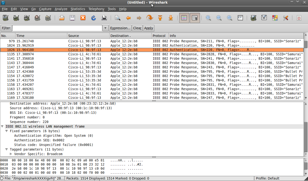
Many access points offer the option to authenticate clients based on their wireless MAC addresses. This prevents the access point from returning a successful authentication result when a client with an unauthorized MAC address attempts to connect to a network.
The following screenshot is a packet capture with an authentication message delivered to an unauthorized client connecting to a MAC-filtered network. As can be seen in the "Status code:" section, the access point issues an "Unspecified failure" result rather than the "Successful" result required for authentication.
"Packet Capture of MAC-Filtered Authentication Attempt" - Kevin Benton
While this security method is widely available, it is considered poor practice to implement.[IV.3] It requires exponentially increasing administration overhead as more clients and access points are added to a network. Furthermore, it is simple to circumvent.
As evident in the screenshot above, MAC addresses are transmitted in cleartext. Anyone could simply run a packet-capture to record the MAC address of an authorized client and configure his or her wireless card to use the authorized MAC address.[IV.3]
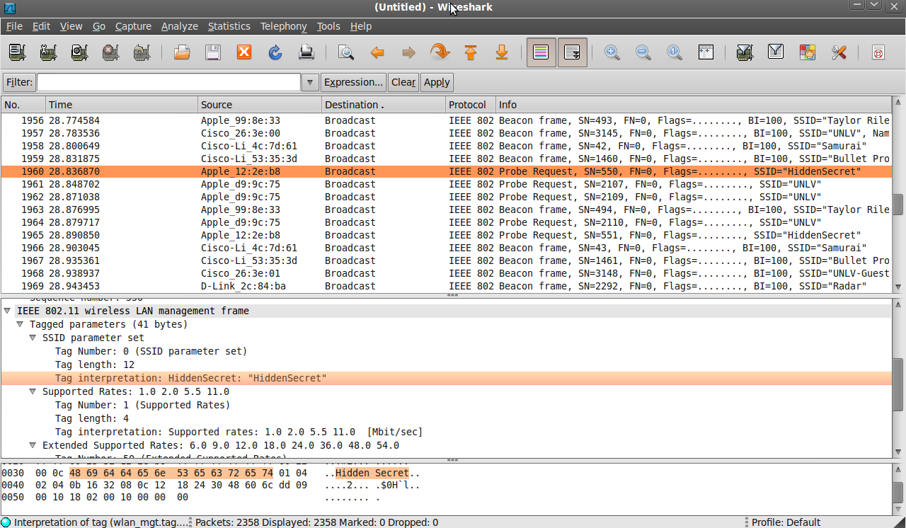
Another security practice that should be avoided is a feature called "SSID hiding". This prevents the access point from advertising the SSID of the network as it normally would using beacon frames. While this does prevent the SSID from showing up in network scanners, it to can be circumvented with network surveillance.
By capturing the traffic between valid clients and the network, the SSID can still be extracted from PROBE requests, PROBE responses, ASSOCIATION requests, and REASSOCIATION requests.[IV.4]
The following screenshot is a packet capture of a client connecting to a hidden wireless network with the SSID of "HiddenSecret". While there weren't any beacon frames revealing the name, it was still easily found in other management frames such as the probe request captured below.
"Packet Capture of hidden SSID association" - Kevin Benton
Not only is this an ineffective measures of security, it can interfere with the ability of clients to properly roam between access points. Clients use the constant beacons from APs in the same ESSID to determine when a stronger signal is available. When SSID hiding is enabled, the client has to actively probe for available APs, creating network congestion.[IV.4]
If the network is configured to use open system authentication in conjunction with WEP, the authentication phase remains the same. The difference occurs when a client attempts to associate with the access point.
In order for the association to be successful, the client needs to be configured with a shared encryption key used for the WEP encryption algorithm. If the client is configured with the wrong key or with no key at all, it will not be able to correctly associate with the network to generate and receive traffic.
Because clients without the correct shared key cannot associate with a network or decrypt its traffic, open system authentication in conjunction with WEP encryption inherently authenticates the client.
Due to this characteristic and a major vulnerability with shared key authentication(covered in the Shared Key Authentication section), open system authentication is always preferred, even when using the WEP algorithm. [IV.6]
While many vendors offer the options to implement SSID hiding and MAC filtering, they should be avoided in implementations. Both are easily circumvented and create unnecessary administrative overhead. If an unencrypted network requires security or authentication, it needs to be implemented at an upper-layer of the OSI. (e.g. IPsec, SSL, captive portals)
The authentication process for shared key authentication starts out with cleartext exchanges similar to the open system authentication process. The key difference is that the client is authenticated using a shared key. This is accomplished in a four-step process.[IV.1]
For the following process, the frames in all of the steps contain the following information:
First, the client sends a frame to the station it wants to join containing the following information:
Second, the receiving station delivers a frame back to the client containing the following information:
The challenge text is a 1024-bit random number that will be used by the client to prove its identity.
Third, the client sends the following information back:
The receiving station decrypts frame 3 using the initialization vector and shared key. It will then perform a WEP ICV check to verify that the message was delivered correctly. If it passes the integrity check, the challenge text is compared to the text sent in frame 2.
If the client did not use the correct shared key, frame 3 will fail the WEP ICV check and will be discarded. (More information on the WEP encryption and ICV check can be found in the Wired Equivalence Privacy section.)
Finally, the receiving station will then send the last frame to finish the authentication process with the following information:
This completes the authentication process, if the parties had keys that didn't match, the result would be unsuccessful and the client would have to start over. Once authenticated, the client is permitted to associate with the access point and begin generating traffic.
Once a client has authenticated, it has the option to encrypt all of the subsequent traffic using WEP with the same shared key. While it is possible to implement shared key authentication without encryption, it should be avoided as it does not provide any protection from eavesdropping. Additionally, the vulnerability discussed in the next section allows an attacker to complete the authentication process without knowing the key.
While the shared key authentication system appeared to offer a valid means of authentication at first, a major flaw was quickly discovered that could allow an attacker to authenticate to the network after capturing a successful authentication process. [IV.5]
The vulnerability discovered relies on the fact that a the authenticator station delivers the challenge text to the client in cleartext. By capturing this challenge text the attacker can construct the what the plaintext response should be; and, by capturing the response from the client, the attacker knows what the ciphertext of the response is.
WEP takes a key-stream generated by RC4 and XORs it with the plaintext bit-by-bit to produce the ciphertext. By knowing the plaintext and the resulting ciphertext, the attacker can reverse the process by performing an XOR on the plaintext and ciphertext to reproduce the key-stream.
The attacker can now request authentication, encrypt the challenge using the derived key-stream, and send it along with the same initialization vector that the previous client chose and successfully authenticate. The following diagram illustrates the attack process.
"Shared Key Authentication Vulnerability" - Kevin Benton
While this attack is simple, it does not award the attacker the encryption key. Therefore, if the network requires encryption in conjunction with shared key authentication, the attacker can not make it beyond the authentication phase without the actual shared key. Various attacks to discover the shared key are covered in the WEP Flaws section.
Due to this vulnerability, shared key authentication should be avoided in WEP implementations. Open System Authentication with WEP encryption accomplishes the same task without revealing a key-stream.[IV.6]
When the IEEE released the initial 802.11 standard, all of the security relied on the Wired Equivalent Privacy(WEP) algorithm. This algorithm was responsible for both authentication and encryption. The name came from the idea that the algorithm would provide the same security attributes inherent to a wired medium.
The original standard only included the option to use a 40-bit encryption key. This key size was chosen because of the US restrictions on exporting cryptography technology at the time. By choosing a small key size, the IEEE hoped to make the algorithm exportable to other countries without modification.[IV.1]
With only a 40-bit key, brute-force attacks were practical for many organizations with access to fairly modest computing power at the time of the release(1999). For this reason, many manufacturers offered an extended 104-bit key(128-bit total with the 24-bit IV) to eliminate brute-force out as a method of attack.[IV.7] All of the text covering the WEP operation covers the 40-bit key; however, the process is identical for 104-bit keys.
The encryption mechanism that WEP employs is the RC4 algorithm from RSA Data Security, Inc.[IV.1] RC4 is a stream cipher, which means that it encrypts each message one bit at a time, as apposed to block ciphers that encrypt groups of bits at a time. The design of RC4 is to simulate a one-time pad.
The one-time pad, or Vernam's Cipher, is an unbreakable encryption method when provided with a truly random key.[IV.8] The key must be at least as long as the data that needs to be encrypted, and both parties must have identical copies of the key. The key must be unpredictable and can never be reused.
Due to these strict requirements, key distribution becomes unfeasible for widespread implementations or the encryption of large amounts of data. Since each message bit requires an individual key bit, encrypting a 4.7GB DVD would require a 4.7GB key.
The idea of RC4 is to simulate a one-time pad by using a pseudo random number generator(PRNG) to produce the key-stream used to encrypt the data. The key-stream produced is controlled by an encryption key. Therefore, the same encryption key always produces the same key-stream. The PRNG is a one-way function in that the key-stream cannot be given to the PRNG to produce the original encryption key.
It accomplishes this by creating an ordered 256-byte array and then randomizing it's contents based on the encryption key's length and value. It then produces a key-stream from the array while continually randomizing the array to prevent the key-stream from repeating.[IV.9]
The encryption operation itself is relatively simple. Each bit of plaintext is XORed with the a bit of the key-stream to produce the ciphertext. The other party then XORs the ciphertext with the the same key-stream to reproduce the plaintext. The only difference between this operation and the one-time pad is the source of random numbers.
Due to the nature of the RC4 algorithm, a single missing bit would cause a misalignment with the key-stream and the stations would no longer be able to communicate. Since wireless frames are expected to be occasionally be lost during transit, the encryption process is restarted for each frame.
Since the RC4 process is restarted for every frame, it would reproduce the same key-stream for every frame. If two frames are encrypted with the same stream, an attacker can XOR both ciphertexts, producing the same result as performing an XOR on both plaintexts(i.e. C1⊕C2=P1⊕P2).[IV.7] By guessing pieces of the original plaintexts, an attacker can quickly discover both of the original plain texts and consequently the key-stream.[IV.7] To prevent this, WEP adds an initialization vector to the encryption key given to RC4 to make each key-stream unique.
This initialization vector(IV) is a 24-bit random number generated by the device every time it has a message to send. This IV is then appended with the shared key(40-bits) to make a key unique to the frame. This unique key is then used to generate the key-stream used to encrypt the message. Since the IV is generated by the device, it has to transmit the IV in cleartext along with the ciphertext so the receiver can construct the correct key-stream to decrypt the message.[IV.1]
Every frame also includes and integrity check value(ICV) that is used to determine if a message has been modified during transit. Before a message is encrypted, the transmitting station calculates the CRC-32 hash of the plaintext message and then appends the output to the original message.
The ICV and payload are then encrypted and transmitted. When the receiver decrypts the message, it calculates the ICV of the plaintext message and compares it to the ICV received. If the values match, the receiver accepts the frame; otherwise, the frame is dropped.[IV.1]
The following diagrams outline the process of encrypting and decrypting frames using the WEP algorithm:
"WEP Encryption and Decryption" - Kevin Benton
One of the simplest flaws of the WEP algorithm is its use of the CRC-32 hashing algorithm for its integrity check value(ICV). CRC is a poor cryptographic hash choice because it is a linear function of the message. This property means that an attacker can flip any bit in the ciphertext and correctly adjust the encrypted hash to avoid detection. This is accomplished with the equation C'=C⊕(Δ,c(Δ)). C is the original ciphertext, C' is the modified ciphertext, Δ is the changes to the original ciphertext and c(Δ) is the CRC-32 value of Δ.[IV.7] This can be accomplished without knowing the plaintext or the key-stream.
As covered in the WEP Operation section, the RC4 algorithm becomes very vulnerable if two messages are encrypted using the same key-stream. To protect against this, the IEEE implemented the 24-bit IV; however, it is now apparent that an IV will most likely be repeated after approximately 5,000 messages due to the "birthday paradox".[IV.7] Once a collision has occurred, an attacker can use the equation "C1⊕C2=P1⊕P2" to get the XOR of the plaintexts.
By making guesses about the contents of the packets using known fields, the attacker can reveal the original plaintext. Another approach is to use statistical based attacks such as character frequency analysis.[IV.10]
Once a plaintext is revealed, the key-stream for the corresponding IV can be found by calculating C⊕P=K(C is the ciphertext, P is the plaintext, and K is the key-stream). The key-stream can then be used to decrypt all of the previous and subsequent packets that use the same IV. However, if the attacker wants to decrypt all traffic, this attack is very slow because he/she would have to calculate the key-stream for every IV. This would require the victim to generate enough traffic to reuse every single IV at least once(2*2^24 possible IVs=33.5 million frames).
One flaw that this attack can quickly exploit relies on the fact that the original 802.11 standard didn't require the IV to be changed for every packet. Since the transmitting station picks the IV, the attacker can reuse the known IV and key-stream to generate an unlimited number of valid frames.
An attacker can also capture frames from a valid client and resend them to the network any number of times and they would be accepted because WEP has no anti-replay counter.[IV.11] These injection vulnerabilities could be used to launch a denial-of-service or to send other malicious traffic into the network without knowing the key. [IV.7]
These basically vulnerabilities were all published by 2001. Several attacks were released in subsequent years to recover the original key progressively faster. However, the most significant attack against WEP was published in 2007, reducing the possible 104-bit shared key recovery time to less than 60 seconds. This attack has a success probability of 50% with less than 40,000 frames, and up to 95% with with 85,000 frames. This attack is an expansion on the Fluhrer, Mantin and Shamir related-key attack and the Andreas Klein RC4 analysis.[IV.11]
This advanced attack requires a large number of frames because it creates a statistical ranking for all of the possible keys. As more frames are collected, keys receive more "votes". The more votes that a key receives makes it more probable to be the original shared key. A key basically gets a vote if it can produce the same partial key-stream found in the captured frames.
The statistical calculations for the voting mechanism are beyond the scope of this paper and can be found in section 3 and 4 of reference 11.[IV.11] The statistical calculations revealing the weaknesses of the RC4 key scheduling algorithm discovered by Fluhrer, Mantin and Shamir that this attack builds on can be found in reference 17. [IV.17]
This rapid attack relies on the predictability of the ARP protocol. Encrypted ARP traffic is easy to recognize because of its fixed sizes of 42 bytes and 60 bytes. They also have fixed 8-byte LLC headers and two possible 8-byte ARP headers depending on if the message is a request or a reply. The attacker can then determine if it is a request or a reply by checking the cleartext destination MAC address. If it is a broadcast address, it is an ARP request message; and, if it is a unicast address, it is a ARP reply.
The attacker can then XOR the known 16 bytes with the first 16 bytes of the captured ARP traffic. This gives the attacker the first 128-bits of the key-stream along with the IV. By collecting enough of these combinations, the attacker can derive the possible shared keys that would generate these key-streams.
In order to speed up this attack, the previously discovered vulnerability of being able to inject traffic without knowing the shared key is exploited. The attacker repeats previously captured ARP requests very rapidly. Each request will yield another response encrypted with a new IV. In tests in the paper, the authors were able to collect 40,492 key-streams in only 53 seconds. Once the keys were collected, the cryptographic recovery computation took only 3 seconds on a 1.7 GHz Pentium-M CPU. [IV.11]
Various flaws have been discovered with the WEP algorithm throughout the last decade. As a result, it is now considered insecure and all implementations should be replaced by security offered by the 802.11i standard. The payment card industry has already banned all future WEP implementations for credit card transactions and ruled that existing implementations have to be replaced by 802.11i by June 30th, 2010.[IV.12]
One more notable attack against the WEP algorithm and its implementation was published in 2007. This attack is called the "Caffe Latte" attack, and the unique attribute of this attack is that it is performed against a client when it isn't connected to the target network.[IV.16] As the name suggests, it could be performed in a coffee shop.
This attack exploits the noisy nature of wireless clients when they are scanning for a network to join. When a client attempts to find networks to connect to, it probes for networks that it was previously configured to join. This includes encrypted and unencrypted networks. If an attacker listens to the probe requests from the client, he/she can setup a fake access point with the same SSID. The client will then attempt to authenticate with the AP, believing that it is a network in its preferred list.
Since the authentication request is sent in cleartext, the attacker can easily determine if the fake network needs to simulate shared key authentication or open system authentication. If the client was configured to use shared key authentication, the original shared key can be discovered in around 20-24 minutes using the following process.[IV.16]
Both of these methods rely on the network being configured to use shared key authentication. This same attack can be applied to open authentication; however, because the attacker cannot derive a valid key-stream, he/she cannot communicate with the client directly and has to rely on the de-authentication frame method to solicit more packets from the client. This slows down the attack even more, and increases the attack time to between 7 and 9 hours depending on how fast the client sends out DHCP or gratuitous ARP requests.[IV.16]
This attack presents another major security concern for WEP encrypted networks. This takes the attack away from the network itself, eliminating protection provided by building security and careful control of broadcast power. The attacker doesn't have to sit in the company's parking lot anymore--just anywhere near an employee's powered on laptop.
A few fixes to the WEP protocol were proposed, but they ultimately fell to the wayside because of the fundamental flaws with the WEP mechanism. A protocol needed to be built from the ground up to replace WEP. This led to the creation of the 802.11i protocol.
WEP2 was proposed as a potential replacement for WEP by extending the shared key length to 128 bits along with 128-bit initialization vectors. Unfortunately, it still allowed IV reuse, which wouldn't protect it from the same traffic spoofing attacks on WEP. It still relied on CRC-32 for the ICV, so frames could be modified without detection. The only benefit was in increased time to discover the keys due to the larger IV and shared key.[IV.11]
WEPplus was an enhancement by Agere Systems to avoid the "weak IVs" discovered by the Fluhrer, Mantin, and Shamir attack.[IV.14] As this was the only improvement it wasn't widely implemented and it was still vulnerable to many of the attacks including the rapid attack discovered in 2007. Newer versions of the Linux kernel(>2.6.20) also automatically avoided the weak IVs after they were discovered in 2001.[IV.11]
Another offered solution was initially titled Dynamic WEP. Several vendors had a proprietary way to implement it, but the idea was basically to give each user a dynamically generated key each time they connected.[IV.15] It was never standardized; however, the general idea was carried over to 802.11i.
Of course WEP can alway be supplemented with adding another layer of security above it such as IPsec or SSL; however, they aren't really considered fixes to WEP as they don't address any of the problems with WEP directly. A user would be just as secure using one of those upper layer security protocols on an entirely unencrypted wireless network. Ultimately, the only way to fix WEP implementations is to replace them with one of the new standardized encryption mechanisms outlined in the 802.11i section of this paper.
With the many vulnerabilities of the WEP algorithm, the IEEE formed Task Group I of the 802.11 working group to replace the original authentication and privacy provided by the initial 802.11 standard.[V.1] The final draft was ratified on the 24th of June, 2004 as 802.11i. On March 8th, 2007, several of the 802.11 standards (a,b,d,e,g,h,i,j) were rolled up into the new base 802.11 standard "IEEE 802.11-2007".[V.2] This entire section of the paper is derived from the security section of the 802.11-2007 document unless otherwise cited.[V.5]
Networks compatible with the new security protocols are referred to as Robust Security Networks (RSNs). Whenever a network is using an RSN protocol, it identifies it by marking RSN bits in the management frame headers. This is necessary because RSN networks introduce an entirely new key management and authentication protocol in addition to new encryption algorithms. Pre-RSN stations can not connect to an RSN network.
An association between two RSN stations are referred to as robust security network association (RSNA). Each RSNA has its own unique set of keys and key lifetimes. The following section describes the new key hierarchy as well as the methods used to derive each key.
One of the biggest changes introduced in the 802.11i standard was the way encryption keys are handled and generated. With WEP, the pre-shared key was immediately appended to the IV and given to RC4 to generate the key-stream. This put a discrete limit on the number of frames that could be encrypted from one pre-shared key without repeating a key-stream.
To fix this limitation, a new key hierarchy was introduced for RSN networks that prevents the re-use of any keys regardless of the chosen encryption algorithm.
There are essentially two possible top level keys that are used to generate the rest of the keys in the heirarchy. In the case of a pre-shared key based network, the top key is simply the pre-shared key(PSK). On the other hand, if the network uses 802.1X authentication, the top key is the master session key(MSK). These keys are used to derive the next key in the list, called the pairwise master key(PMK).
In the PSK scenario, the PSK simply becomes the PMK. In the 802.1X scenario, the PMK is derived from a section of the MSK. This section is dependant on the extensible authentication protocol(EAP) method used for 802.1X. Once the PMK has been derived, all of the subsequent key derivations are the same for both 802.1X and PSK networks.
The next key is the pairwise transient key(PTK). This key is specific to the client and the AP that it communicates with. Therefore, if all of the clients use the same PMK (i.e. a PSK-based network) they will still derive different PTKs. The PTK is also unique to each assocation; so, every time a client associates with an AP, it will derive a different PTK.
The problem with maintaining an individual key with each client becomes apparent when dealing with multicast and broadcast traffic. If N clients are associated, the AP would have to retransmit the frame N times, encrypting it with a different key each time. To avoid this, the AP generates a random group master key(GMK). Every time a client associates or disassociates, the AP derives a new group transient key(GTK) from the GMK. This GTK is delivered to each one of the clients to be used to encrypt and decrypt multicast and broadcast traffic.
The final keys in the heirarchy are the EAPOL-Key Key Confirmation Key(KCK), EAPOL-Key Key Encryption Key(KEK), and the temporal key. The KCK and KEK are used to protect EAPOL-Key frames. The temporal key is the one that is used with either TKIP or CCMP to protect regular network traffic.
The following diagram illustrates the key hierarchy for reference during the next sections of the paper describing the key derivation processes:
"RSNA Key Hierarchy" - Kevin Benton
EAPOL-Key frames are special key management frames used by stations to derive key information and establish secure communication. They are are also used to update expired temporal keys between associated stations.
As covered in the hierarchy above, the EAPOL-Key frames are protected by keys independent of the temporal key used to encrypt normal traffic. This provides a secure means of communicating new keying information if the temporal key expires or becomes compromised.
The EAPOL-Key frames are protected by a 128-bit key confirmation key(KCK) and a 128-bit key encryption key(KEK). These keys are used in one of the two following combinations of algorithms:
As seen above, the EAPOL-Key frames have a complex set of security protocols to allow stations to exchange keying information in a secure method independent of the method used to encrypt normal traffic.
Even if an attacker could collect enough data frames to discover the temporal key, he or she would still not be able to read EAPOL-Key frames. Therefore, the attacker would have to start over whenever the temporal key expires and the stations re-key.
Many of these keys in the hierarchy require hundreds of bits of material each. When someone uses a PSK like "supersecret", it needs to be expanded to the number of bits required for all of the algorithms. In order to accomplish this, the standard defines a pseudo random function(PRF) that can generate key-streams of length 128, 192, 256, 384, or 512 bits.
The PRF accomplishes this by using the SHA-1 hashing algorithm on the input, which produces a 160-bit stream. It then repeats the process, appending the output to the stream each time until it produces enough bits for the required output.
Different lengths are required depending on the use of the key-stream. The reasoning for the lengths are as follows:
Based on these requirements, the following table shows which lengths the PRF needs to generate for each type of transient key.
TKIP TK | CCMP TK | KCK | KEK | Total Bits Required | |
TKIP PTK | 256 | 128 | 128 | 512 | |
CCMP PTK | 128 | 128 | 128 | 384 | |
TKIP GTK | 256 | 256 | |||
CCMP GTK | 128 | 128 |
"PRF Output Length Requirements" - Kevin Benton
The 192-bit length is also defined in the PRF; however, it currently isn't used anywhere in the 802.11 standard. The TK length requirements for TKIP and CCMP are covered in their respective sections. The GTKs do not require the KCK or KEK because EAPOL-Key frames are not broadcast or multicast.
The method that clients and access points follow to derive these transient keys and establish communication is known as the 4-way handshake.
The pairwise transient key(PTK) is one of the most important keys because it is used to establish the initial secure connection between a client and an access point.
The PTK is derived using the PRF function with an output length of either 384-bits or 512-bits depending on whether the network uses CCMP or TKIP, respectively. The following is a list of the inputs into the PRF:
The resulting PTK is then broken into the following three keys:
Each side exchanges random numbers and computes the PTK. Since the PTK was generated using the PRF with MAC addresses and random numbers as input, it is unique to the client/AP pair. Therefore, traffic encrypted by keys derived this PTK cannot be decrypted by other clients in the same network. For this reason, another key needs to be generated to encrypt and decrypt multicast/broadcast traffic. This key is called the group temporal key(GTK).
The GTK is derived in much simpler process because it can be delivered and protected by the EAPOL-Key frames. The AP maintains a randomly generated group master key(GMK), which it then uses as input to the PRF along with a random number to generate the GTK. The PRF generates either 128 bits(for CCMP) or 256 bits(for TKIP).
Once the access point has generated the GTK, it encrypts it and sends it to each station on the network protected by EAPOL-Key frames. If any station leaves the network, the AP generates a new GTK from the GMK and a new random number. This prevents stations from eavesdropping on the broadcast/multicast traffic after they leave the network.
The following diagram depicts the entire 4-way handshake that clients go through to establish a connection to an AP:
"4-way Handshake" - Kevin Benton
Once this process is complete, normal traffic can pass encrypted by either TKIP or CCMP.
In a PSK network, all of the clients end up with same PMK; therefore, any client can derive the PTK for any other client if it captures the random variables during the handshake. To prevent eavesdropping among clients on the same network, 802.1X authentication can be used instead of a PSK. While the setup is more complicated, it results in unique PMKs for every client, greatly increasing the security of the network.
Other than the cryptographic weaknesses of the original 802.11 standard, it also lacked a method for enterprises to maintain large numbers of wireless clients. With the only standard option being a PSK, every single client had to be configured with a PSK prior to connecting to the network. If even one machine became compromised, all of the machines using the key had to be reconfigured.
The 802.11i task force fixed this by integrating the 802.1X authentication standard along with the original pre-shared key architecture. With the new authentication mechanism, key management and access control can easily be controlled from an authentication server.
The authentication server maintains encrypted channels to all of the access points in a network by means outside the specifications of 802.11. Most vendors use the RADIUS protocol for this purpose. The Remote Authentication Dial In User Service(RADIUS) protocol provides accounting, authentication, and authorization in a central location. It was standardized by the IETF in RFC 2865.[V.4]
When 802.1X authentication is used, it occurs immediately after a client associates before the 4-way handshake. The authentication process on an 802.11 network is comprised of these three main steps:[V.7]
The following diagram briefly outlines the above process during a successful 802.1X authentication process:
"Successful 802.1X Authentication" - Kevin Benton
Not only does this process afford the extra security of dynamic keys, it greatly simplifies the management of network access. If a user needs to be blocked from accessing the network, his/her credentials can simply be disabled on the server. If it were a PSK-based network, all of the keys would have to be changed on the clients and APs.
As noted before, 802.1X authentication results in unique MSKs for every client, subsequently making the PMKs unique to every client. This eliminates the ability for valid clients to eavesdrop on traffic from other valid clients.
Once the stations have established all of the required keying material, they can finally move on to encrypting regular traffic. The 802.11i standard introduced two new encryption algorithms: the Temporal Key Integrity Protocol (TKIP), and the Counter Mode with Cipher Block Chaining Message Authentication Code Protocol (CCMP).
CCMP was designed from scratch to avoid all of the vulnerabilities discovered with WEP. However, CCMP uses the AES block cipher instead of the RC4 stream cipher, which WEP hardware was not designed to handle. Therefore, TKIP was also included to afford previously deployed hardware better security than WEP.
TKIP was designed to replace WEP in existing wireless hardware that couldn't handle CCMP. Due to the processing limitations of early wireless network interface cards, the new protocol had to meet several design constraints. These constraints allowed pre-802.11i equipment to use TKIP with a new driver or firmware update.
The design constraints can be divided into these three major components:[V.3]
With these design constraints in mind, TKIP was developed as a suite of enhancements to WEP. These three new pieces are designed to fix WEP's vulnerabilities without obsolescing previously deployed hardware:
Each process was designed to fix a specific vulnerability or set of vulnerabilities with the WEP protocol. The following sections will cover each process in more detail, followed by how they all fit together in the TKIP protocol.
One of the key issues that made the attacks against the WEP algorithm was the ability for an attacker to inject traffic into the network without being detected. This posed many attack risks beyond the discovery of the pre-shared key. In order to fix this problem, the "Michael" message integrity check was created to detect packet injections.
WEP's integrity check relied on an unsigned CRC-32 checksum to detect changes. This checksum wasn't encrypted with any key independent of the key-stream. The stations simply calculated the checksum and encrypted it with the rest of the packet. the attacker only had to know one valid key-stream to create messages, calculate the checksum, and encrypt the message.
The other problem with the CRC-32 checksum was its predictability even when encrypted. Without knowing a single key-stream, an attacker could arbitrarily flip bits in an encrypted message and correct the encrypted checksum to avoid detection.
To fix these problems, the MIC uses a key independent of the one used to encrypt the final message. The key is 64-bits long and is broken up into two 32-bit halves to create a message signature in the following steps:[V.3][V.5]
This output isn't predictable and can't be easily generated without knowing the correct MIC key. This mitigates the two WEP vulnerabilities mentioned above. Even with this new algorithm, the authors predicted that it would be inadequate at providing protection from brute-force attacks due to its small key size. For this reason, separate MIC keys are used for transmitting and receiving and a strict countermeasure is implemented for detected failures.
If two MIC failures are detected within one minute, it is considered an attack and the station disassociates for 60 seconds and and then re-associates. Consequently, new keys are generated for encryption and the MIC. This makes it extremely difficult for the attacker to gain any knowledge about the keys. While this behavior is quite disruptive, it was considered better than allowing the attack to reveal anything more about the keys.[V.3]
TKIP has such a low threshold for failed MICs because the odds of a transmission error causing a MIC failure are extremely low. The payload and the MIC are still encapsulated by WEP; therefore, an error would have to pass the frame-check sequence and the WEP CRC-32 check before making it to the TKIP MIC.
Even with low CPU intensity calculations, the MIC is the most computationally expensive part of the TKIP algorithm. On ARM7 and i486 processor based access points, the users will receive a performance degradation—even at 802.11b rates.[V.3] However, there is no other alternative for effective layer 2 security that can be deployed on these older pieces of hardware.
The MIC provides protection against packet forgeries; however, it doesn't make use of any type of sequence number to prevent replay attacks. To prevent these replay attacks, a TKIP Sequence Number(TSC) is use to keep track of each MAC Protocol Data Unit(MPDU) sent to the WEP algorithm.
Since the MIC is implemented at the MSDU level, all of the MPDUs containing a piece of the same MSDU have to be received, reassembled into an MSDU, and pass the MIC check before replay detection can occur. This prevents an attacker from causing the TSC to be incremented without a valid MIC key.
Special processing considerations for the TSC have to be implemented when a network uses the 802.11e quality-of-service extensions. With 802.11e enabled, it is possible for frames to get reordered before transmission to favor high priority traffic.
The stations have to maintain a separate TSC for each priority level to prevent legitimately reordered frames from being discarded. This allows stations to maintain replay protection when 802.11e is being utilized.
If an MSDU passes the MIC check, the TSCs associated with the MPDUs it was delivered in are checked to make sure they are greater than the previously received TSC for that priority. If they are, the recorded TSC is incremented and the MSDU is accepted. If they aren't, the MSDU is discarded and the recorded TSC remains the same and it is considered a replay attack.
The station keeps track of how many replay attacks have been attempted during the lifetime of an association.[V.5] Contrary to packet forgery attempts, there aren't strict counter-measures for packet replays because an attacker doesn't gain any knowledge about the keys during the attack.
One of the major problems with WEP was its direct use of the pre-shared key for the RC4 encryption process. The the pre-shared key was simply concatenated to a random IV and then given as input to the RC4 algorithm to generate the key-stream. The consequence was the same key-stream whenever an IV was repeated.
The new RSNA key hierarchy already offers a lot of protection from this problem due to the fact that it does not send the PSK directly to the encryption algorithm. Instead, it offers the temporal key that can be periodically regenerated. However, TKIP also employs more key mixing functions to make it extremely difficult for an attacker to derive the temporal key, let alone the PTK or GTK from which it was derived.
The first phase of the key mixing algorithm uses the 128-bit temporal key, the transmitter MAC address, and the 32 most significant bits of of the TKIP sequencing counter(TSC) to produce an 80-bit "TKIP-mixed Transmit Address and Key(TTAK)". Since the TSC is 48 bits total, the TTAK will only need to be refreshed every 2^16(65,535) frames.
The TTAK is produced in phase 1 with these two sub-steps:
Phase 2 of the key mixing function produces the 128-bit WEP seed that is passed on to the WEP algorithm to encrypt the packet. In this phase, the inputs used are the TTAK, the temporal key, and the 16 least significant bits of the TSC. Since the 16 least significant bits of the TSC will change with every frame, the WEP seed will be uniquely generated for every frame.
The WEP seed is produces in phase 2 with these three sub-steps:
The WEP seed is then passed on to the WEP algorithm to be used as the IV and the encryption key. It is important that the least significant bits of the TSC are in the 1st and 3rd octet, because the first 3 octets will become the cleartext IV. The 32 most significant bits of the TSC are also transmitted in an extended IV field in cleartext. This allows the receiver to check the TSC without decrypting the packet to detect replay attacks and generate new TTAKs whenever the 32 most significant bits of the TSC change.
The entire key mixing process results in a unique encryption key for every frame that is transmitted. Between the key mixing processes and the RSNA key hierarchy, there are essentially three layers of protection between the original key and the key used to actually encrypt the data.
After the 4-way handshake is completed, a 256-bit temporal key will be given to the TKIP algorithm. The first 128 bits will be used as the temporal key for encryption. The remaining 128 bits will be split into two 64-bit MIC keys. The first key signs and checks data from the AP to the client, and the second signs and checks data from the client to the AP.
The following diagram illustrates the TKIP encryption process:
"TKIP Encryption" - Kevin Benton
The decryption process is basically the reversal of this process with extra checks.
Currently, the only know vulnerabilities with TKIP allow for a very limited rate of frame injection. The two attacks are known as the Beck-Tews[V.8] attack and the Ohigashi-Mori[V.9] attack.
This attack relies on the network having the 802.11e QoS enabled so that there are 8 TSC counters being tracked by the stations. It also assumes the attacker knows the first 3 octets of the IP address of the network being attacked. With these two conditions met, the attack can continue.
Much like with many of the WEP attacks, the attack captures the traffic until an encrypted ARP request is discovered. These packets are easy to detect because of their very specific length and the destination always being the broadcast address. Once an ARP request is discovered, all of the information except for the last octet of the source IP, the last octet of the destination IP, the 8 byte MIC and the 4 byte WEP ICV.
The attacker then XORs the known information with the captured packet. The resulting information is nearly the complete key-stream. The bytes for the IPs, MIC, and ICV are still unknown.
The attacker then uses the Chopchop attack[V.8] to guess the values of the remaining key-stream. The specific details can be found in the reference, but the attacker essentially removes an unknown byte of the message, and then corrects the CRC based on a guess of what the unknown byte was. The client will silently drop the packet if the guess was wrong because the CRC will fail; however, if the guess was right, the TKIP MIC will fail and the client will send out a MIC failure frame.
The attacker will send all 255 possibilities until the MIC failure is detected. The attacker then knows the correct value of the unknown byte and can follow the same process with the next unknown byte. The attack takes a little more than 12 minutes to reveal the values of the 8-byte MIC and 4-byte ICV. After generating the MIC failure, the attacker has to wait 60 seconds to avoid triggering TKIP forgery countermeasures.
Once the attacker knows the MIC and the ICV, the last octet of each IP address can be guessed and just checked against the ICV. Once the attacker has the full plaintext of the packet, the Michael algorithm can be reversed to reveal the MIC key. Michael wasn't designed to be a one-way function so the process is very simple.
Now that the attacker has a key-stream and the MIC key, a frame can be generated that will pass the MIC check. The only remaining protection is the TSC. This is where the QoS channels come into play. In most cases, only one QoS priority is used, so the recorded TSCs for the other 7 priorities will be much lower than the one the frame was captured on. The attacker can then safely send a frame to the client using one of each of the other QoS priorities without being detected.
Subsequent key-streams can be derived in 4-5 minutes because the attacker now knows the MIC key, so only the ICV has to be derived from the Chopchop method. The attacker can then guess the IP octects, checking the resulting MIC with the ICV locally.
The scope of this attack is very limited as it allows, at best, slightly over one frame per minute to be sent to the client. While this could be used to falsify an ARP message for a man-in-the-middle attack, the attacker would need to have a machine on the same LAN to direct the traffic to, in which case the machine on the LAN could perform the attack itself.
Mitigations for this attack include disabling the unused QoS settings or disabling the MIC failure notification that lets the attacker know when the guess was correct. Alternatively, the lifetime of the PTK can be reduced to a few minutes, causing a new temporal key and MIC keys to be generated before the attack can complete.
This attack is essentially an expansion on the Beck-Tews attack that allows for operation in a network that does not have QoS enabled. The attacker conducts a man-in-the-middle attack by impersonating the AP to get the client to connect to it. It then acts as a relay for all of the traffic so the client appears to be communicating with the AP.
The attacker then waits for an ARP message and then blocks it and all subsequent messages to the client from the AP. The Beck-Tews attack is then implemented to recover the MIC key and the key-stream. Then the attacker can send one falsified message to the client.
Some shortcuts to the process were also introduced that reduce about 37% of the attacks to approximately 1 minute . While this is an vast improvement over the original Beck-Tews attack it still only affords about 1 frame per minute to be sent to the client without QoS enabled.
Another downside to the attack is the noticeable way in which is interrupts the client's traffic. For the attack to occur, the client can not receive any traffic from the AP. This would be very apparent to the user if network services were being used and it may cause the user to re-associate or disconnect entirely.
Mitigations for this attack also include reducing the lifetime of the PTK and disabling the MIC failure notification.
Overall, the TKIP algorithm accomplished its task. Its purpose was to allow old wireless hardware to operate securely for the rest of its life cycle. The algorithm should no longer be used and it will be deprecated in the next release of the 802.11 standard.[V.10]
Counter mode with cipher-block chaining message authentication code(CCMP) provides the highest level of confidentiality, integrity and replay protection available in the 802.11 standard. It relies on the advanced encryption standard(AES) algorithm using a 128-bit key with a 128-bit block size. There are currently no feasible attacks against the CCMP algorithm other than brute-force attacks attempting to discover weak PSKs.
CCMP makes use of a standard referred to as Counter with CBC-MAC(CCM) which is defined in RFC 3610.[V.11] It can be used with any 128-bit block ciphers; however, CCMP specifies AES as the block cipher.
One of the requirements for CCMP is a number that is unique to every frame(nonce). This is accomplished with the use of a 48-bit packet number(PN) that is incremented for every transmitted frame.
The PN is then combined with the source MAC and the QoS priority to produce a 104-bit nonce. This nonce is then sent to the AES algorithm along with the 128-bit key and data to be encrypted. Depending on the mode of operation, the nonce may need to be padded with zeroes.
The advanced encryption standard(AES) is a block cipher that was released by the National Institute of Standards and Technology in 2001. This was after a 5-year standardization process where 15 competing algorithms were evaluated to determine which one would become AES. The final chosen algorithm was Rijndael. The document that details its operation is FIPS PUB 197.[V.13]
AES encrypts data in blocks of 128 bits using a key size of either 128, 192, or 256 bits. The 128-bit data is arranged into a 4x4 array referred to as the state. The key is then broken into round keys using a key schedule.
For a 128-bit key(the size used for CCMP), the state goes through 10 rounds substitution boxes, row shifts, column mixing, and XORing with the round key. Once the final state table is reached, it is returned as the ciphertext.
As of now, there aren't any effective attacks against the AES algorithm itself. There are some attacks referred to as side channel attacks that exploit the device performing the encryption to reveal the key.[V.14] However, they require the ability to execute code on the device so they do not affect the implementation in 802.11.
AES has held its ground after 13 years of scrutiny by the cryptographic community; however, if a vulnerability were discovered, CCM is designed in such a way that changing block ciphers would be relatively trivial.[V.11]
The modes of operation refer to the way that inputs are delivered to the AES algorithm. AES encrypts 128-bit blocks of information at a time so a message needs to be broken into 128-bit blocks and encrypted. There are several methods to doing this, each one producing different outputs.[V.12]
The most straight forward method is called electronic codebook(ECB). ECB directly encrypts each data block using the key. The problem with this procedure is that repeating input blocks produce repeating cipher text. Because this method reveals information about patterns in the original data, it shouldn't be used in any cryptographic algorithms.
There are two modes of operation used in CCMP: cipher-block chaining and counter mode. Both of these methods require some type of initialization vector in addition to the key. In the case of CCMP, this initialization vector is the nonce value.
Cipher-block chaining takes the nonce delivered to it and pads it with an extra 24 bits to bring its size up to 128-bits. It then uses the nonce and the temporal key to encrypt data in the following process:
Each block using the previous block's ciphertext is what "chains" the blocks together.
Counter mode takes the 104-bit nonce and then adds a 24-bit counter to the end of it. The counter is initially set to zero. Messages are encrypted in the following process:
In contrast to cipher-block chaining, the blocks don't rely on the ciphertext of the previous blocks to be encrypted. This makes counter mode less computationally expensive.[V.12]
The following diagram illustrates both block cipher operation modes:
"Block Cipher Modes"- Kevin Benton
CCMP protects the integrity of the payload along with various fields in the header. The protected fields are referred to as additional authentication data(AAD). This AAD protects the following information: all of the address fields, the fragment number, and the QoS identifier.
The AAD is concatenated with the payload and sent to the AES algorithm along with the temporal key and the nonce. To generate the MIC, the AES is used in cipher-block chaining mode.
The last block of ciphertext produced in this mode is a function of all of the ciphertext blocks before it. Therefore, a single bit change in any of the inputs would drastically change the final block of ciphertext, making it a good MIC. This final block is 128-bits; however, it is truncated to the first 64-bits before being returned.
The MIC is appended to the payload and then encrypted by AES in counter mode using the nonce and the temporal key.
The encryption and decryption process are relatively simpler than the TKIP process. The encryption is completed using the following steps:
The following diagram illustrates the process:
"CCMP Encryption" - Kevin Benton
The red arrows are for the MIC generation step and the green arrows indicate the encryption step.
The decryption is completed using the following steps:
The following diagram illustrates the process:
"CCMP Encryption" - Kevin Benton
In this case the packet is decrypted before calculating and checking the MIC. The Key ID isn't visible in this diagram; however, it is checked to select the correct temporal key.
CCMP is the strongest privacy and protection offered by the 802.11 standard and it has been proven to be very effective at accomplishing its task. The weakest link is when the user selects a pre-shared key. A poor choice of the pre-shared key such as "password" can be discovered by a brute-force dictionary attack.
By using a strong pre-shared key or 802.1X authentication, CCMP in unfeasibly crackable because the only option becomes checking 2^128 possible keys. At a rate of even 1 billion keys per second, it would take approximately 10^20 centuries to crack.
The Wi-Fi alliance is a non-profit organization that was formed in 1999 with the goal of creating a worldwide certification for high-speed wireless local area networking.[VI.1] Even though the IEEE released the 802.11 documents, they did not include provisions for testing standards compliance.
The organization was originally founded by six companies in 1999 under the name "Wireless Ethernet Compatibility Alliance (WECA)". The purpose at this time was to guarantee compatibility between 802.11b vendors. Even though products from different vendors were all based on the 802.11b standard, many did not work together.[VI.2] The group was then renamed to "Wi-Fi Alliance" in 2002 and it now contains over 300 companies.[VI.3]
The group coined the term "Wi-Fi" for vendors to place on products to indicate that they had passed the compliance tests set by the the Wi-Fi alliance. The first testing began in March of 2000, and, as of 2009, over 1 billion wireless chipsets bearing the Wi-Fi certification have been sold.[VI.1]
Once a product passes the certification process, the vendor is allowed to package it with a variation of the famous Wi-Fi logo(pictured below) depending on the radio type of the device.
"Wi-Fi CERTIFIED logo" - Wi-Fi Alliance
Any products that are certified by the Wi-Fi alliance are compatible with all products bearing the same certification, along with previous certifications in the same frequency band. Therefore, 802.11n products with Wi-Fi certification are also backwards compatible with 802.11b products and 802.11g products, as they all operate in the 2.4Ghz spectrum.[VI.4] This important feature prevents companies from being required to upgrade all of their infrastructure at once to support a client with an 802.11n card. On the other hand, a single 802.11b client would require an 802.11n access point to reduce to 802.11b speeds, impacting all of the users.
The Wi-Fi certification process involves the several sub-categories, many of which are optional. The following is a list of the current categories:[VI.5]
Only the first three categories are required for a device to receive the basic Wi-Fi certification. If a device qualifies for additional categories, it will receive the additional corresponding certifications. The certifications are conducted by at least one of the 13 independent test laboratories around the world. [VI.5]
The Wi-Fi Protected Access(WPA) certification was first developed when the 802.11i revisions were still being made to the standard. It was released as soon as possible because of the apparent security flaws with the WEP algorithm. It implements most, but not all of the standard. Most noticeably, the CCMP algorithm was not yet included.[VI.7]
One of the extra things that WPA offered outside of the 802.11i standard was special handling of the pre-shared key. One of the concerns with TKIP and CCMP is the users poor choice of a PSK.
Normally, the PSK would be sent directly to the PRF-384 or PRF-512 function to generate the PTK. In WPA compliant devices the key is first expanded using the PBKDF2 key derivation function in the following manner:[VI.8]
This makes it very difficult to derived the PSK that was entered by the user from the PSK actually used in the PRF function to derive the PTK. Mixing in the SSID also adds another layer of security against tables of known keys.
WPA2 was introduced in 2004 and requires all of the revisions introduced in 802.11i document. As of 2006, all new devices have to be WPA2 compliant to bear the Wi-Fi logo.[VI.7]
The WPA and WPA2 standard also define the EAP methods that are allowed for 802.1X authentication. The 802.11i revisions only specified that EAP method had to mutually authenticate the user and the server. The following EAP methods are allowed by the WPA2 standard:[VI.9]
Overall, WPA2 includes everything in the 802.11i standard plus a few extra added requirements and enhancements. If a client were completely 802.11i compliant, but not WPA2 compliant, it wouldn't be able to connect to a WPA2 network even though it uses all of the underlying protocols.
WPA2 has become the de-facto standard for wireless equipment. Any wireless hardware that doesn't meet the standard should be avoided at all costs. It won't likely work with nearly all of the deployed wireless equipment.
Wi-Fi Protected Setup was introduced by the Wi-Fi alliance in 2007 to simplify the configuration of WPA2 in small networks. It allows users to configure a secure network without knowing about SSIDs, pre-shared keys, or encryption types. The three configuration methods are "Personal Identification Number", "Push Button Configuration", and "Near Field Communication Token".[VI.6][VI.10]
The PIN method requires a user to read a PIN number off of his/her wireless adapter and enter it on the interface of the wireless access point. The access point then generates EAPOL keys based off of the PIN. The client will have generated the same keys based off the been and can then establish secure EAPOL messaging with the AP. The AP with then deliver the correct keying information to the client and it will re-associate with the network.
The push button configuration allows the user to push a button on the access point and then push a real or virtual button for his/her wireless adapter at the same time. The AP and the client then recognize each other and generate pre-shared keys. During this generation time, the network is vulnerable to eavesdropping.
The near field communications token relies on an out-of-band transmission medium such as an RFID tag. The user simply places their wireless adapter near the access point, and the AP will read the keying information from the RFID tag. It can then use this to establish a secure EAPOL messages and deliver the network keying information to the client.
Overall, Wi-Fi protected setup hasn't been deployed to widely. The Wi-Fi alliance shows that 700 devices have the certification.[VI.6] It is good for inexperienced users; however, it doesn't scale well into larger networks. Mixing in devices that don't support it could become a management hassle. There is also no standard built into the operating system network managers for it yet. Each vendor usually has a custom interface for the activation. The following is an example of one such interface:
"Wi-Fi Protected Setup" - http://i44.tinypic.com/akjzue.jpg
The Wi-Fi alliance is one of the biggest reasons for the worldwide deployment of 802.11 networks today. The marketing of the term "Wi-Fi" has been very effective and nearly every mobile computer user knows what it means.
Additionally, the certification process that permits equipment to bear the Wi-Fi logo has kept hardware manufacturers in check. It keeps users from worrying about whether or not their Linksys adapter will connect to a Netgear access point.
Kevin Benton UNLV Informatics-Spring 2010